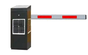
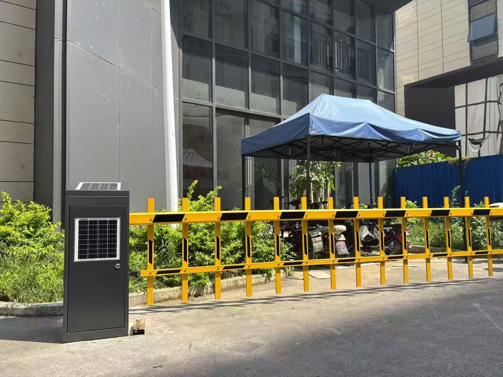
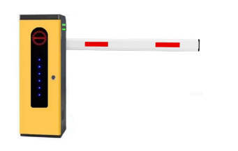
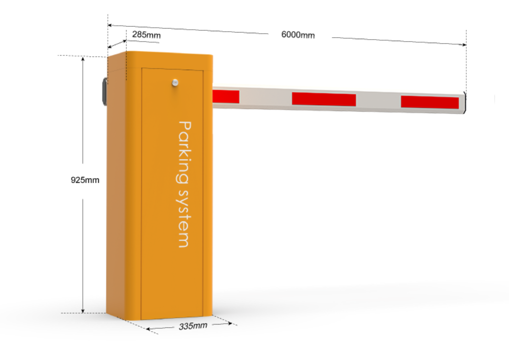
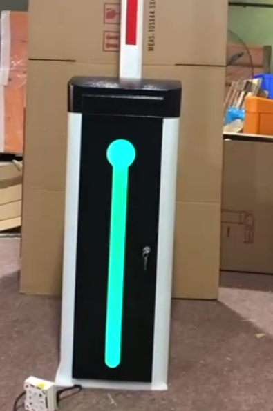
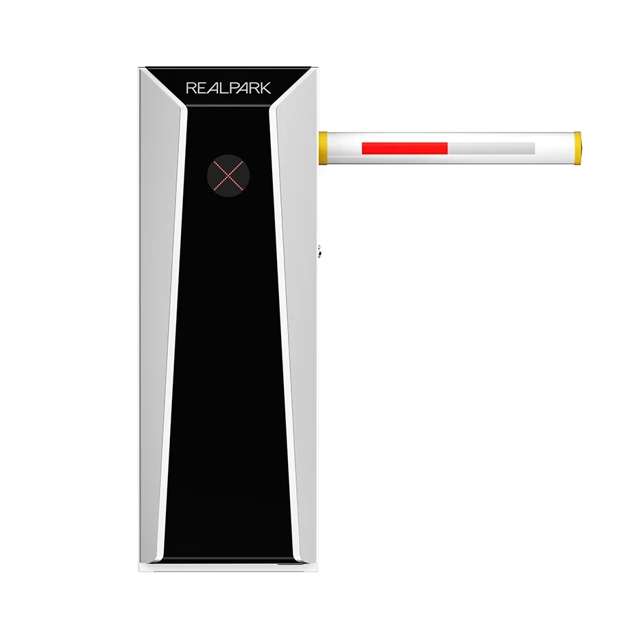
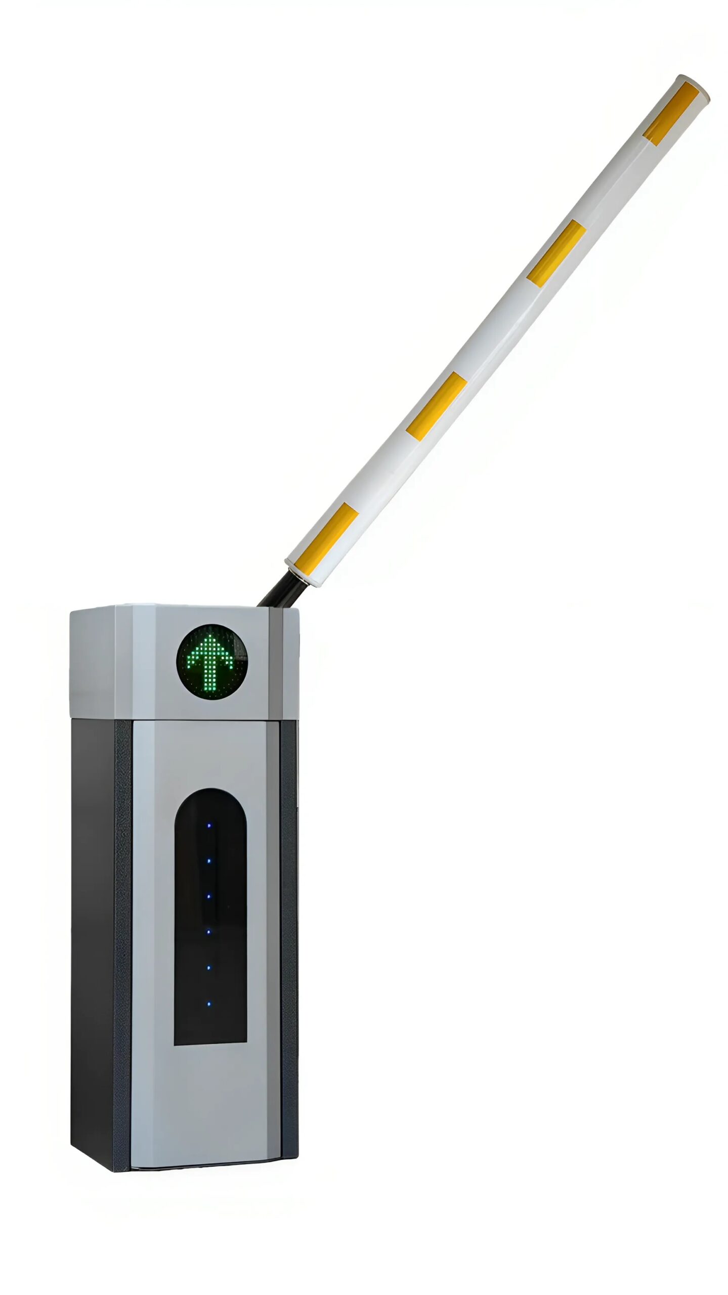
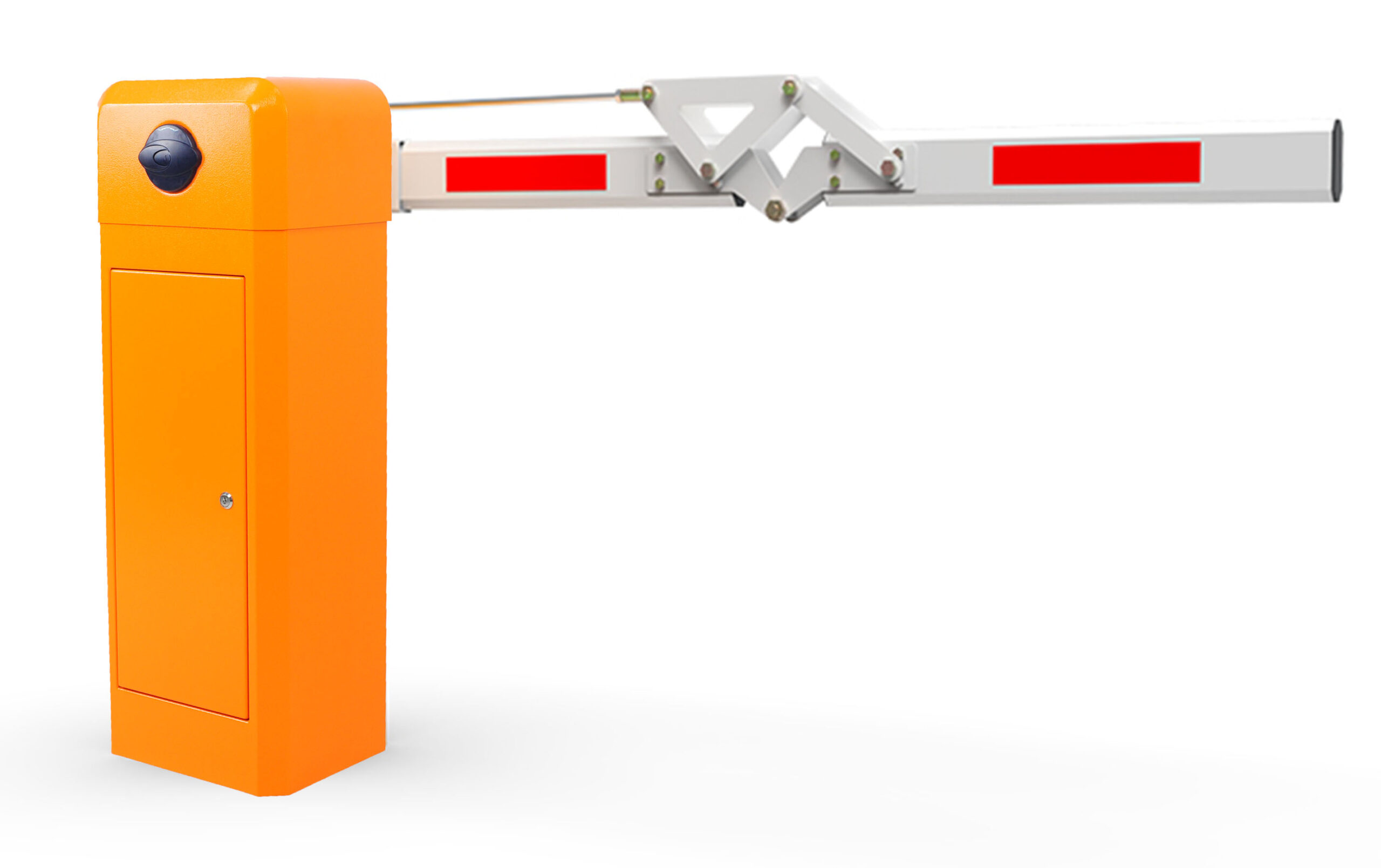
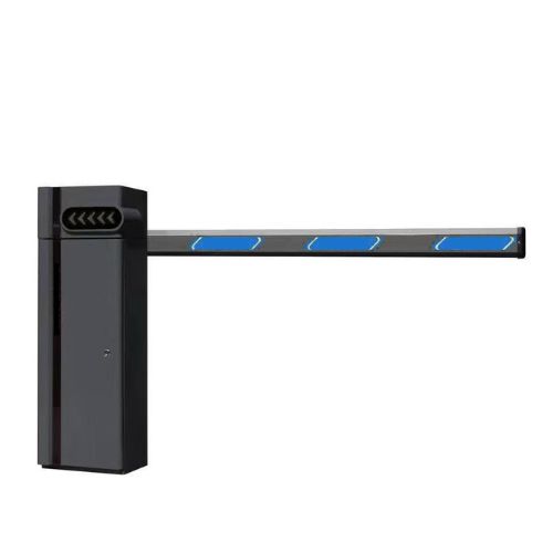
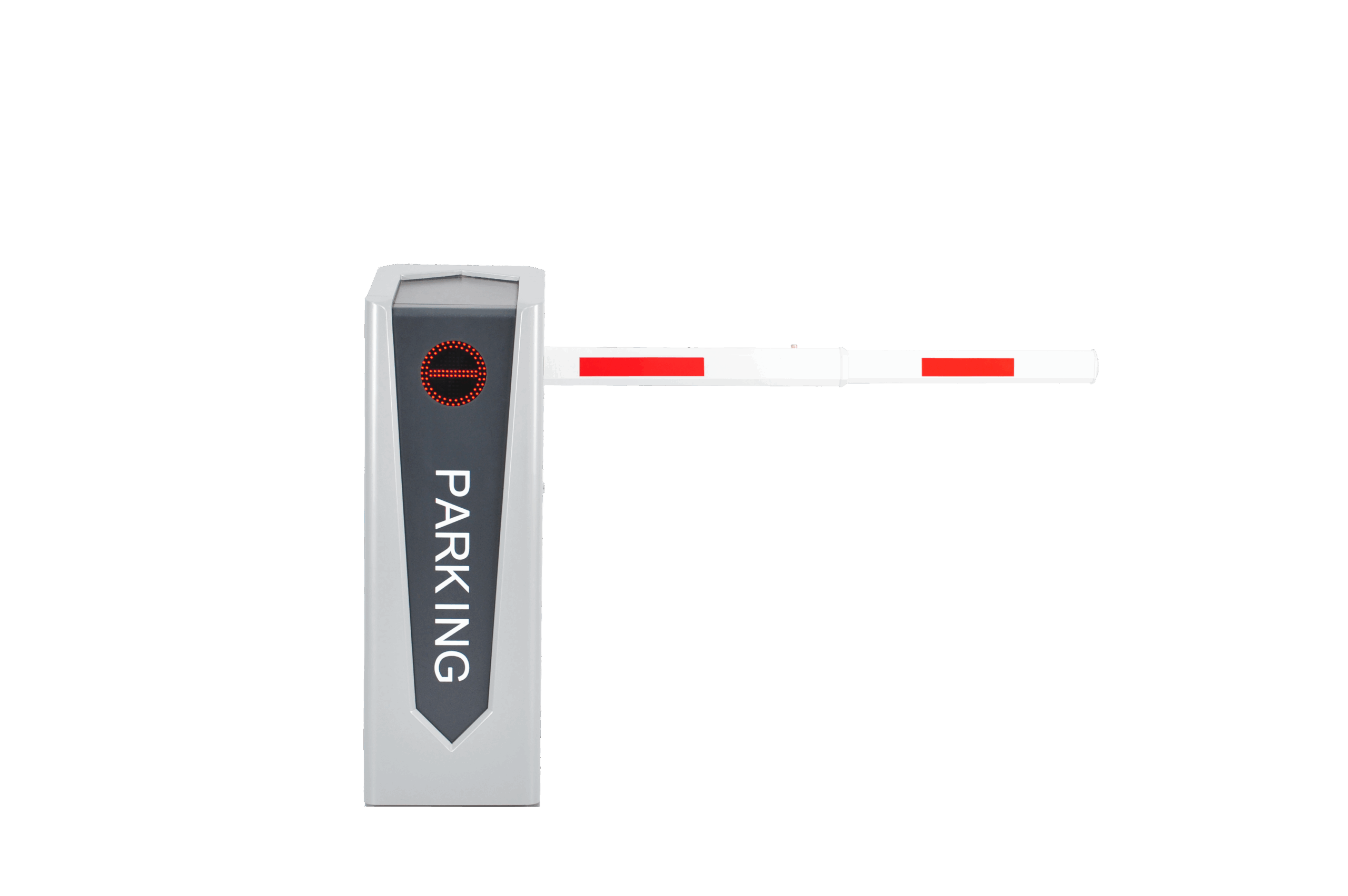
Chassis Size : 380*390*1070mm
Color : Black
Chassis Thickness : 1.5mm
Open Time : 2 – 6s (adjustable)
Motor Power : 120W – 150W (Optional)
Working Power Supply : 220V
Operating Temperature : -40 – +85℃
Remote Control Distance : ≥ 30m
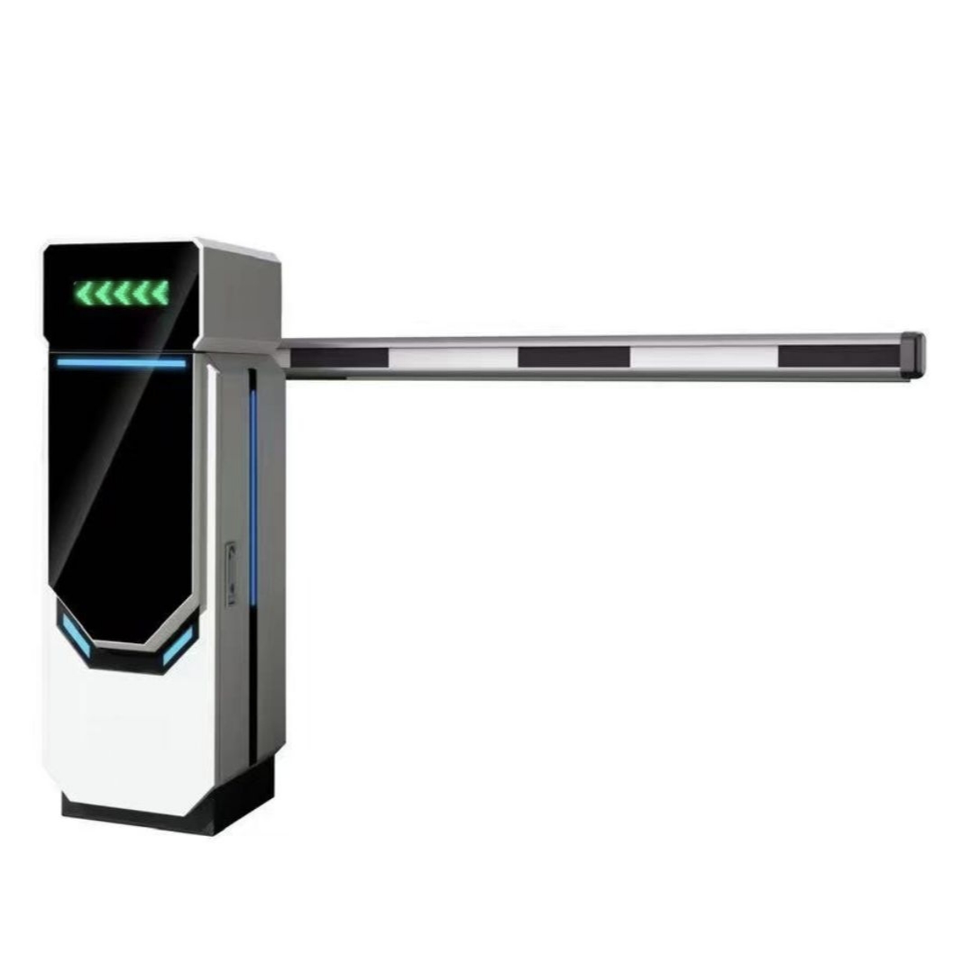
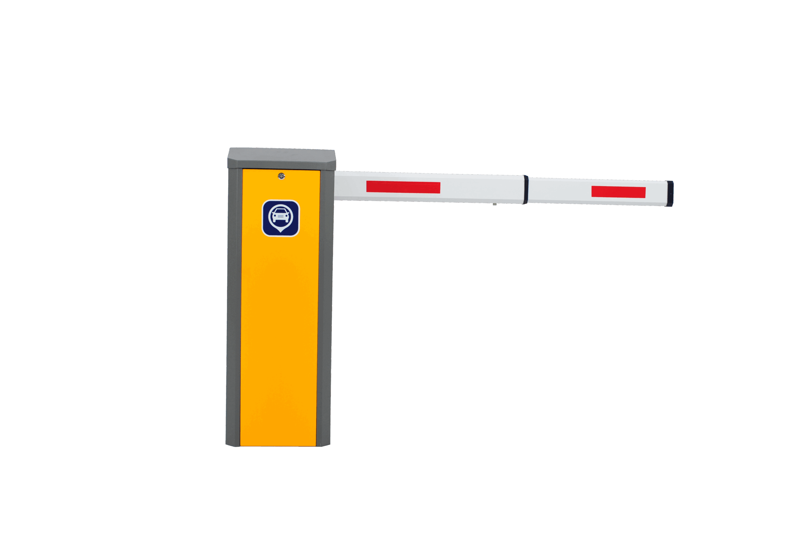
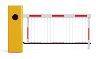
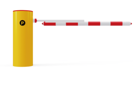
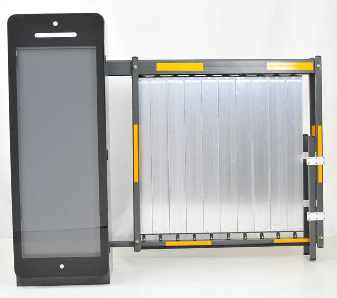
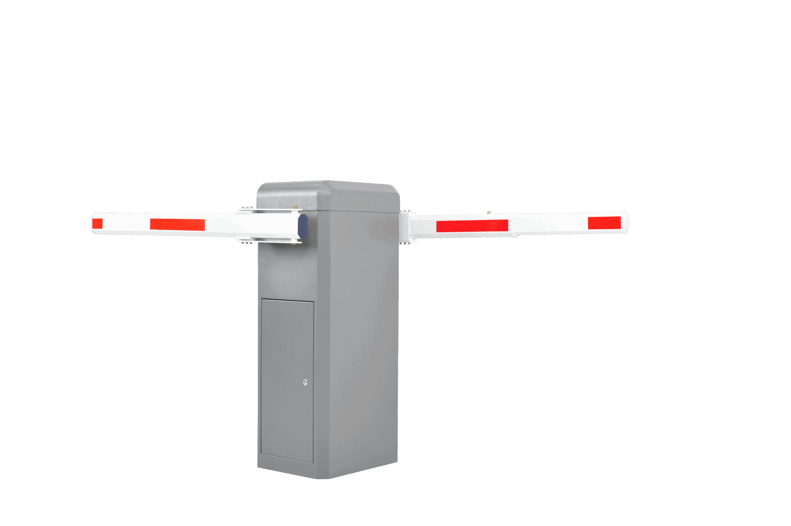
Arm Optional : Straight / Telescopic Arm, Folding Arm, FenceArmBoom direction Exchangeable
MTBF : 10 million cycles


- Control System Inputs: The battery and photovoltaic (PV) charging inputs are independently controlled. A 20kA lightning protection switch is integrated into the PV input to prevent lightning damage. A 24V voltage regulator stabilizes the PV load output to avoid gate malfunctions due to overvoltage. The system supports upgrades to Bluetooth, Wi-Fi, or 4G IoT for remote monitoring of gate charging/discharging and operation.
2. Power-On Sequence: The gate operates in pure DC mode and must be powered on in the 1-2-3-4 sequence of the main control system in PV conversion mode. Do not activate the PV charging switch first under strong sunlight, as this may prevent charge storage and damage the converter.
3. PV Conversion Settings: The PV system is factory-configured for the battery model and charging mode. Do not modify these settings.
4. Learning Stroke: Ensure the gate rod is properly installed. Start the self-test and stroke learning by pressing the menu key for 2 seconds to access the main menu (“Pxx” display). Navigate to “P00” using the open gate/+ or close gate/- keys, then press confirm to display 000 or 001. Press open gate/+ or close gate/- to make the gate rod move between open and closed limits. The “OFF” display indicates successful stroke learning. Relearning is unnecessary unless the E05 error appears or the gate malfunctions. If the mechanical origin is not detected, check battery charge and voltage. The 24V regulator requires a 1-minute boot-up before performing a self-test
V. Remote Control Learning and Deletion
5.Accessing the Menu: Enter the main menu, navigate to “P01” using the Open/+ or Close/- buttons, and press Confirm. If “000” is displayed, no remote controls are learned. All learning and deletion occur in the P01 menu.
Learning a Remote Control:
6.Press Open/+ briefly; the first digit on the display flashes. Press the remote’s Open button for >1 second. A buzzer confirms learning.
7.The second digit flashes. Press the remote’s Close button for >1 second. The buzzer confirms.
8.The third digit flashes. Press the remote’s Stop button for >1 second. The buzzer confirms, and the display shows “001” (first remote learned).
9.For additional remotes (up to 50): Press Open/+ briefly; all digits flash. Press any Open, Close, or Stop button on the remote. The buzzer confirms, and the display increments (e.g., “002” for the second remote).
10.Deleting a Single Remote: Press Close/- briefly; all digits flash. Press any Open, Close, or Stop button on the remote. The buzzer sounds, and the display decrements by 1, confirming deletion.
11.Deleting All Remotes: Press and hold Close/- for >5 seconds. All digits flash, the buzzer sounds, and the display shows “000,” indicating all remotes are deleted.

The battery pack comes standard with 5V/5A.12V/5A.24V/20A regulated output, and the charging has overcharge protection function. Each group of output is independently controlled, and comes standard with aviation interface output, which is stable and durable.